
The 177230 Seismic Transmitter: Your Gateway to Actionable Machine Health Data
In today’s data-driven industrial landscape, capturing accurate machine health signals is non-negotiable. The Bently Nevada 177230 Seismic Transmitter simplifies this task by delivering reliable, continuous vibration data directly to your control system. This robust, loop-powered device translates physical casing motion into a standardized 4-20 mA signal, bridging the gap between complex machinery and actionable insights for plant engineers and reliability teams.

Core Technology: From Mechanical Motion to Process Signal
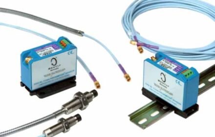
The 177230 is a velocity-based transducer. Inside its stainless-steel housing, a seismic mass moves within a magnetic coil in response to casing vibration. This motion generates a voltage signal internally conditioned into two outputs: a primary 4-20 mA analog signal representing overall vibration severity, and a secondary buffered dynamic signal for detailed waveform analysis. This dual-output design supports both basic alarming and advanced diagnostics.
Seamless Integration: The Universal 4-20 mA Advantage
Integration simplicity is a key strength. The 4-20 mA output is the universal language of industrial control. It connects directly to any Programmable Logic Controller (PLC) or Distributed Control System (DCS) analog input module without needing intermediate monitors or complex configuration. This plug-and-play capability drastically reduces installation time and cost, making continuous monitoring feasible for hundreds of balance-of-plant assets.
Technical Specifications for Reliable Performance
Built for industrial duty, the transmitter’s specifications ensure longevity and accuracy:
- Measurement: Casing vibration velocity (in/s RMS or mm/s RMS)
- Frequency Range: 4.5 Hz to 1,000 Hz
- Output: 2-wire, 4-20 mA (loop-powered), plus buffered dynamic signal
- Power Supply: 12-30 VDC (sourced from the loop)
- Housing: Stainless steel, weatherproof and corrosion-resistant
- Mounting: ¼-28 UNF stud mount
Enabling Proactive Predictive Maintenance
Moving from reactive to predictive maintenance requires trendable data. The 177230 provides exactly that. By feeding a continuous 4-20 mA signal into a historian, plants can establish baselines and set intelligent alarms. A gradual rise from 8 mA to 12 mA over six months on a pump bearing housing, for example, clearly indicates developing wear, allowing maintenance to be scheduled weeks in advance, avoiding unplanned downtime.
Expert Insight: The Cost-Benefit of Widespread Deployment
At Oiltech Controls, we analyze total cost of ownership. For a critical turbine, a full monitoring system is justified. For the dozens of pumps and fans supporting it, the economics shift. The 177230 allows you to instrument these assets at a fraction of the cost. We’ve seen clients achieve a 300% ROI within 18 months by preventing just one unexpected failure per year across a fleet of 50 monitored pumps. Its value lies in scalable, reliable data collection.
Application Case: Solving a Chronic Pump Failure in a Chemical Plant
A chemical plant had a cooling water pump that failed every 9-12 months, causing a 2-day production loss each time. They installed a 177230 transmitter. The 4-20 mA trend in the DCS showed vibration slowly climbing from 0.2 in/s to 0.7 in/s over 8 months. Spectral analysis of the buffered output revealed a rising 2x running speed component, indicating misalignment. During the next planned outage, realignment was performed. The pump has now run for over 24 months without issue, saving an estimated $180,000 in lost production and repair costs.
Application Case: Monitoring Remote, Unmanned Compressor Stations
A natural gas pipeline operator needed to monitor reciprocating compressors at remote, unmanned stations. They installed 177230 transmitters on each compressor frame. The 4-20 mA signals were transmitted via RTU to a central SCADA system. When vibration on Unit 3 exceeded the 15 mA alert threshold, a crew was dispatched. They found a loose foundation bolt that, if left unchecked, could have led to a catastrophic frame crack. The remote monitoring prevented a potential $500,000 asset loss and environmental incident.
Installation and Configuration Best Practices
- Mounting Location: Choose a rigid, flat spot on the bearing housing, perpendicular to the shaft axis. Avoid flexible panels or areas with high local resonance.
- Surface Preparation: Clean the mounting surface to bare metal to ensure a solid mechanical connection.
- Wiring: Use shielded, twisted-pair cable for the 4-20 mA loop. Ground the shield at the DCS/PLC end only to prevent ground loops.
- Scale Configuration: In the DCS, scale the 4-20 mA signal to engineering units (e.g., 4 mA = 0 in/s, 20 mA = 1.0 in/s) based on the transmitter’s range.
- Alarm Setting: Set initial alarms per ISO 10816 standards for the machine type, then refine based on historical trend data.
Frequently Asked Questions (FAQ)
What is the difference between the 177230-01-01-05 and other model suffixes?
The suffix indicates specific options like connector type, cable length, or hazardous area certification. The “-01-01-05” is a common industrial configuration. Always check the datasheet to match the model suffix to your environmental and electrical requirements.
Can I get frequency spectrum data from the 4-20 mA signal?
No. The 4-20 mA signal is an overall vibration level. For spectrum analysis, you must use the buffered dynamic output (available via a test connector on the transmitter) with a portable analyzer or online data collector.
How do I perform a basic field check of the transmitter?
With the machine stopped, the 4-20 mA output should read a very low value (near 4 mA, representing 0 vibration). Gently tap the transmitter housing. You should see a momentary spike in the mA reading on your DCS trend or a handheld meter in the loop, confirming the sensor and signal path are alive.
Is the 177230 suitable for very low-speed machinery (below 300 RPM)?
Its low-frequency limit is 4.5 Hz (270 RPM). For machinery below this speed, consider a specialized low-frequency sensor. For most pumps and motors above 300 RPM, it is perfectly suitable.
What maintenance does the transmitter itself require?
Virtually none. It is a solid-state device with no moving parts. Periodic verification involves checking the mounting bolt tightness and ensuring the electrical connections are clean and secure. The loop can be verified with a mA calibrator.
To implement a cost-effective vibration monitoring program with genuine Bently Nevada components, partner with the application specialists at Oiltech Controls.


