


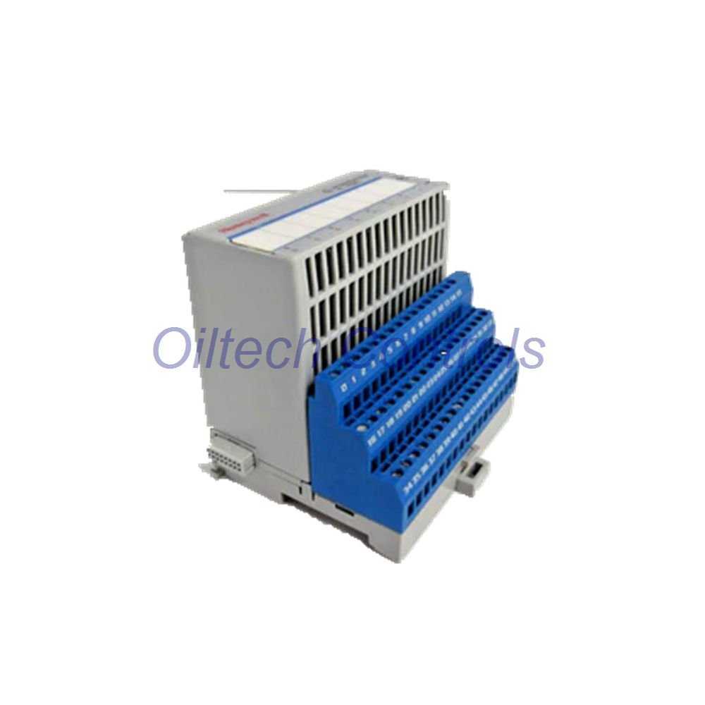
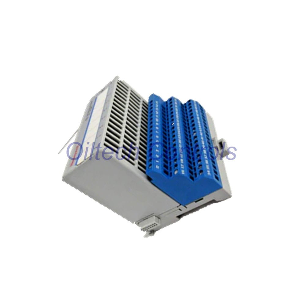
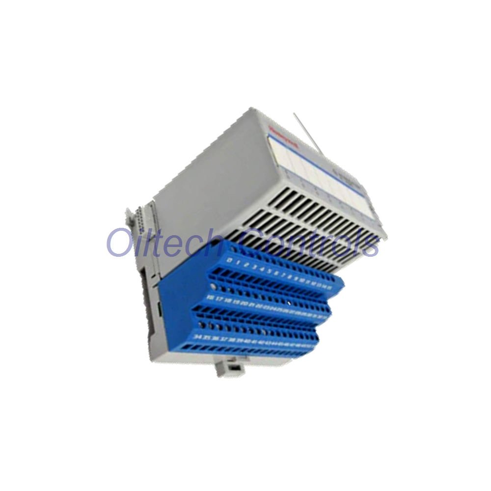

Product Description
TC-POA081 is an 8-point analog output module from Honeywell. It provides 4–20 mA and 2–22 mA extended output. Additionally, each channel supports 2-wire field devices. Moreover, the module is designed for intrinsically safe applications in process control. Therefore, it delivers high accuracy and fast response for critical loops. Furthermore, it suits both new installations and retrofit projects. In addition, it integrates with existing Honeywell backplanes.
This module uses a vendor-specific bus for intrinsically safe input. Outputs share a common reference through sense resistors. However, galvanic isolation separates output from backplane bus and power supply. Also, no isolation exists between output channels. Consequently, users must observe common reference wiring during commissioning. Meanwhile, shielded cable reduces electromagnetic interference.
Technical Specifications
| Brand | Honeywell |
| Model | TC-POA081 |
| Series | Analog Output Module (8-Points) |
| Output Channels | 8 dual-ended, common referenced over sense resistors |
| Output Type / Load | 0 to 500 ohms |
| Signal Range | 4 to 20 mA (normal); 2 to 22 mA (extended) |
| Voltage Output | >11 V @ 22 mA |
| Accuracy | 0.1% of signal range |
| Resolution | 13 bits |
| Response Time | 4 ms to 99% of final value |
| Temperature Drift | 100 ppm/°C |
| Transmission Error @ 20°C | 0.1% of output signal range |
| Transmission Temp Drift | 0.01%/K of output signal range |
| Isolation (Output / Backplane) | Galvanic, per DIN EN 50 020 |
| Isolation (Output / Power) | Galvanic, per DIN EN 50 020 |
| Operating Temperature | –20°C to 70°C (–4°F to 158°F) |
| Storage Temperature | –20°C to 100°C (–4°F to 212°F) |
| Maximum Humidity | 95%, non-condensing |
| Shock Test | 15g peak, 11 ms |
| Vibration Test | 2g @ 10–500 Hz, IEC 68-2-6 |
| Pollution Gas Test | G3, ISA-S71.04-1985 |
| Protection Class | IP20 (IP54 housing required for field installation) |
| Power Consumption | 0.77 power supply unit load |
| Power Dissipation | 5.4 W |
| Dimensions (H x W x D) | 76 x 94 x 46 mm (3.0 x 3.7 x 1.8 in) |
| Weight | 0.274 kg (0.60 lb) |
| Keyswitch Position | 4 |
| Intrinsically Safe Output | Europe: II (1) 2G EEx ia/ib IIB/IIC T4 (CENELEC) |
| Permissible Field Circuit Values (2-Wire) | Uo = 21V; Io = 93mA; Po = 520mW |
| Max Inductance (Lo) | 10 mH for EEx ia IIB; 3 mH for EEx ia IIC |
| Max Capacitance (Co) | 1.27 µF for EEx ia IIB; 188 nF for EEx ia IIC |
| Input Voltage Rating | Intrinsically safe power via Terminal Base |
| Fault Detection | Lead breakage: ≤2 mA; alarm via backplane bus and red channel LED |
| Lead Breakage Detection | Configurable for channel groups 0-1, 2-3, 4-5, 6-7 |
| Latch Mode | Configurable for channel groups 0-3 and 4-7 |
| I/O Terminal Assignments (2-Wire) | Ch0 – 0,1; Ch1 – 4,5; Ch2 – 8,9; Ch3 – 12,13; Ch4 – 17,18; Ch5 – 21,22; Ch6 – 25,26; Ch7 – 29,30 |
Installation Guide
Mount the module on a compatible terminal base. Use shielded multcore cable with a shield for each channel. Moreover, ensure channel isolation exceeds 500 V for EMC protection. Connect 2-wire field devices according to the terminal assignments. Also, verify keyswitch position 4 before power-up. Furthermore, use an IP54 housing or better for field installation. Therefore, follow these steps to avoid wiring faults. In addition, check terminal tightness after mounting.
Commissioning and Maintenance
Configure lead breakage detection for channel groups 0-1, 2-3, 4-5, and 6-7. Set latch mode for groups 0-3 and 4-7 as needed. Meanwhile, monitor the backplane bus for alarm signals. A flashing red channel LED indicates a fault. However, no galvanic isolation exists between outputs, so observe common reference wiring. Therefore, regular inspection of cable shields and terminal tightness is recommended. Consequently, maintenance intervals should reflect site conditions. Additionally, log all alarm events for trend analysis.
Compatibility Notes
The module operates with intrinsically safe power through the terminal base. It uses a vendor-specific bus for intrinsically safe input. Additionally, galvanic isolation applies between output and backplane bus, and between output and power supply. For CE conformity, use shielded multcore cable with per-channel shield. Consequently, channel isolation must be greater than 500 V. Also, confirm terminal base compatibility before installation. Moreover, verify backplane firmware versions for full feature support.
Certifications
CENELEC (Europe): II (1) 2G EEx ia/ib IIB/IIC T4. Marked for all applicable directives. DMT 99 ATEX E 027 X. Moreover, it conforms to DIN EN 50014:1992, DIN EN 50020:1994, DIN EN 50284:1997. Climatic conditions per DIN IEC 721. Also, EMC per DIN EN 50081-2, DIN EN 50082-2, NAMUR NE 21. Furthermore, these approvals support use in hazardous areas. Therefore, confirm local code compliance before commissioning.
Diagnostic Capabilities
Lead breakage detection triggers below 2 mA. Alarm signals travel via the backplane bus. Additionally, the channel LED flashes red for fault indication. Detection and latch modes are configurable by channel groups. Therefore, these features simplify troubleshooting and reduce downtime. Moreover, group-level configuration speeds up commissioning. Consequently, maintenance teams can isolate faults quickly.
Packaging and Shipping
Package includes one Honeywell TC-POA081 module. Shipping via FedEx, UPS, or DHL. Moreover, tracking is provided. Also, a 12-month warranty covers defects in materials and workmanship. Contact us for freight quotes and expedited options. Therefore, confirm shipping details before order placement. In addition, request insurance for high-value orders.
Typical Applications
- Intrinsically safe analog output for process control
- 2-wire field device actuation in hazardous areas
- Legacy Honeywell control system upgrades
- Oil and gas, chemical, and petrochemical plants
- Retrofit projects for obsolete I/O modules
FAQ
Q: What is the maximum load per channel?
A: 0 to 500 ohms.
Q: Does this module provide channel-to-channel isolation?
A: No. Outputs share a common reference through sense resistors.
Q: How do I detect a broken lead?
A: Lead breakage is detected below 2 mA. Additionally, the channel LED flashes red and an alarm goes to the backplane bus.
Q: What is the response time?
A: 4 ms to 99% of final value.
Q: Is the module intrinsically safe?
A: Yes. Moreover, it carries CENELEC II (1) 2G EEx ia/ib IIB/IIC T4 approval. Therefore, it suits hazardous-area installations. Furthermore, it meets DIN EN and NAMUR standards.
Why Buy From Oiltech Controls?
- 15+ years of industrial automation spare parts experience
- Global shipment support with FedEx, UPS, and DHL
- Tested industrial surplus and refurbished options
- 12-month warranty on every module
- Technical verification before shipment
- Support for obsolete control systems
Inquiries: info@oiltechcontrols.com | +86 158 8020 0923
Copyright © 2026 Oiltech Controls Limited. All rights reserved.
Original Source: https://www.oiltechcontrols.com/
All rights reserved.


Reviews
There are no reviews yet.