
Integrating 190501 Sensors with 3500 Systems: A Practical Guide
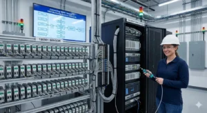
Upgrading machinery protection often involves retrofitting modern sensors into legacy monitoring racks. A common industrial automation challenge is connecting a Bently Nevada 190501 velocity transducer to an existing 3500 system. Success requires precise technical alignment, not just physical wiring. Consequently, neglecting compatibility checks risks faulty data and potential hardware damage.
Understanding the 3500 System’s Input Architecture
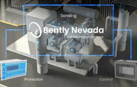
The Bently Nevada 3500 is a modular machinery protection system. Its individual monitor cards are designed for specific signal types. Therefore, a 3500/42M seismic monitor, for example, processes vibration velocity or acceleration. However, each input channel must be configured for the correct sensor technology to ensure accurate data for the plant’s control systems.
Analyzing the 190501 Sensor’s Output Signal
The 190501 is a passive piezoelectric velocity transducer. It generates a low-impedance voltage signal proportional to casing vibration. Importantly, it does not require external power. This contrasts with active sensors needing excitation current. Understanding this distinction is vital for factory automation integration.
The Critical Step: Hardware Configuration & Jumper Settings
Direct connection is possible only with correct hardware setup. The 3500 monitor card’s input channel must be configured for a passive velocity signal. This typically involves setting internal jumpers to disable the IEPE constant current source. Incorrect jumper settings cause sensor fault alarms or erroneous readings.
Software Configuration for Accurate Data Scaling
After hardware, software configuration is essential. The 3500 Configuration Software must define the channel as a velocity input. Moreover, engineers must enter the exact sensitivity from the sensor’s calibration sheet. This ensures the PLC or DCS receives vibration data in correct engineering units.
Wiring and Grounding Best Practices
Proper installation prevents signal noise. Use shielded, twisted-pair cabling for the connection. Additionally, ground the cable shield at the rack end only. This practice minimizes electromagnetic interference in the control systems environment, preserving data integrity.
Expert Insight: Avoiding Common Retrofit Mistakes
At Oiltech Controls, we frequently troubleshoot integration issues. A common error is assuming all vibration inputs are the same. The 190501’s passive output is incompatible with a channel set for active accelerometers. Always verify jumper settings and software parameters. This due diligence prevents costly commissioning delays.
Application Case: Cooling Tower Fan Monitoring Retrofit
A chemical plant needed to monitor a critical cooling tower fan (85 RPM) with their existing 3500 rack. They selected a 190501-08-00-00 for its low-frequency response.
Challenge: The existing 3500/42M card was configured for accelerometers.
Solution: Technicians reconfigured the channel jumpers for passive input and updated the software sensitivity to 500 mV/in/s.
Result: The system provided stable velocity trends, detecting a 0.3 in/s rise that indicated fan blade imbalance. This early warning allowed planned correction, avoiding a $25,000 bearing failure and unplanned downtime.
Verification and Commissioning Protocol
After installation, perform a validation test. Gently tap the sensor housing while observing the real-time waveform on the 3500 software. A clean, sharp spike confirms proper signal transmission. Furthermore, verify alarm setpoints trigger correctly in the DCS before final handover.
Frequently Asked Questions (FAQ)
1. Can I use a 3500/42M card for both 190501 sensors and standard accelerometers?
Yes, but not on the same channel simultaneously. Each channel must be individually configured via jumpers and software for its specific sensor type.
2. What is the maximum cable length for a 190501 sensor to a 3500 rack?
For reliable signal integrity, keep cable runs under 300 meters (1000 feet). Use high-quality shielded cable for longer distances to prevent signal attenuation.
3. Does the 190501 sensor require periodic recalibration?
The sensor itself is stable, but the loop should be verified annually. Check the output against a portable calibrator to ensure the 3500 system’s readings remain accurate.
4. Can I connect a 190501 to a 3500 system originally designed for proximity probes?
Yes, but you must use a 3500/42M or similar seismic monitor card, not a proximity input card (e.g., 3500/40M). The card type must match the signal physics.
5. What happens if I connect a 190501 to a channel with IEPE excitation enabled?
The sensor will likely be damaged, or the channel will fault. The constant current source can overload the passive sensor’s internal circuitry, leading to permanent failure.
For expert support on sensor integration and genuine Bently Nevada components, consult the engineering team at Oiltech Controls.


