
Mastering Fault Diagnostics with the Honeywell CC-PFB801 Communication Module
The Vital Role of CC-PFB801 in Honeywell DCS Reliability
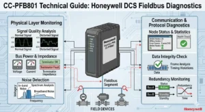
The Honeywell CC-PFB801 communication module serves as a critical bridge within modern control systems. It offers robust Fieldbus connectivity, specifically engineered to manage complex industrial automation networks. In high-stakes sectors like oil and gas or chemical processing, identifying slave device disconnections is paramount. This module utilizes a sophisticated Diagnostic Buffer to capture “slave offline” alarms instantly. Consequently, operators can resolve communication failures before they escalate into costly plant shutdowns.
Leveraging the Diagnostic Buffer for Rapid Troubleshooting
The CC-PFB801 Diagnostic Buffer records every communication event with high-precision timestamps. This feature allows engineers to perform forensic analysis on intermittent faults, such as EMI interference or loose connectors. By reviewing these time-stamped logs, you can distinguish between a complete power loss and a simple protocol timeout. Therefore, troubleshooting becomes a data-driven process rather than a guessing game. Furthermore, these traceable records help facilities comply with strict industrial reliability and safety standards.
Optimizing Communication Cycle Times and Watchdog Settings
System stability often depends on the balance between responsiveness and tolerance. The CC-PFB801 allows engineers to fine-tune communication cycles and watchdog timeout parameters. A shorter timeout provides a faster alarm response for critical factory automation loops. However, excessively tight settings may trigger nuisance alarms in noisy environments. Our experts at Oiltech Controls Limited recommend adjusting these values based on network length and local electromagnetic interference (EMI) levels to ensure peak performance.
Ensuring Protocol Compatibility and Network Stability
Interoperability is a cornerstone of the CC-PFB801 design, primarily supporting PROFIBUS protocol variants. This compatibility ensures that the Honeywell DCS can communicate seamlessly with a wide array of third-party field devices. Nevertheless, engineers must realize that legacy slave devices might not support advanced diagnostics. In such instances, the Diagnostic Buffer might only display generic timeout errors. As a result, maintaining a modern fleet of field instruments is essential for maximizing the module’s visibility.
Best Practices for Installation and EMI Mitigation
Field experience shows that a significant portion of communication errors stems from poor physical layer installation. To maintain fieldbus integrity, always implement 360-degree shield grounding at both ends of the cable. Additionally, avoid routing signal cables alongside high-power motor lines in the same tray. At Oiltech Controls Limited, we have observed that secure, vibration-resistant connectors significantly reduce intermittent “node timeout” alarms in compressor and pump rooms.
Technical Implementation Checklist
- ✓ Verify Grounding: Ensure 360-degree shielding to block electromagnetic interference.
- ✓ Check Connectors: Use integrated locking mechanisms to prevent vibration-induced disconnects.
- ✓ Tune Timeouts: Configure watchdog timers according to the specific node count and cable distance.
- ✓ Protect Logic: Install external surge suppressors for long-distance outdoor cable runs.
Strategic Insights from Oiltech Controls Limited
From our perspective at Oiltech Controls Limited, the CC-PFB801 is more than a simple gateway; it is a vital diagnostic tool for predictive maintenance. The shift toward Industry 4.0 requires deeper visibility into the field layer. While older modules simply “fail,” the CC-PFB801 explains why the failure occurred. We suggest that procurement teams prioritize this module during system upgrades to future-proof their DCS architecture against evolving operational demands.
If you are looking to enhance your system reliability with genuine Honeywell parts, visit Oiltech Controls Limited for expert support and global delivery.
Frequently Asked Questions (FAQ)
Q1: Why does my CC-PFB801 show “Node Timeout” even when the device is powered on?
This usually indicates physical layer degradation or mismatched baud rates. Check for loose terminal connections or excessive EMI near the cable path. In many cases, increasing the retry limit or slightly extending the watchdog timeout can stabilize the connection without compromising safety.
Q2: Can I use the CC-PFB801 with legacy PROFIBUS-DP slave devices?
Yes, it is generally backward compatible. However, keep in mind that older devices may not provide “extended diagnostics.” This means the Diagnostic Buffer will alert you that the slave is offline, but it might not provide specific internal device error codes.
Q3: How does the CC-PFB801 handle multiple slave failures simultaneously?
The module processes events sequentially in its buffer. During a major network disturbance, it will log each node’s departure time. This sequential logging is invaluable for identifying if a specific segment or a repeater is the root cause of a mass disconnection.
Application Scenario: Chemical Plant Uptime
In a recent chemical refinery project, intermittent slave drop-outs were causing recurring process interruptions. By utilizing the CC-PFB801 Diagnostic Buffer, the maintenance team identified that faults coincided with the start-up of a large VFD-driven pump. Consequently, they improved the shielding and grounding for that specific segment. This data-backed intervention eliminated the “slave offline” alarms and saved the facility hours of manual inspection time.


