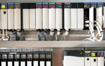
How to Implement Voting Logic on the Bently Nevada 3500/32M Relay Module
In the world of industrial automation and machinery protection, system reliability is paramount. The Bently Nevada 3500 system remains the industry standard for monitoring critical assets like turbines and compressors. A frequent technical inquiry involves whether the 3500/32M Relay Module supports “voting logic,” such as 2-of-3 (2oo3) or 2-of-4 (2oo4) configurations. This article clarifies how to leverage these features to prevent costly false trips while ensuring failsafe protection.

Does the 3500/32M Support Native Voting Logic?
Technically, the 3500/32M Relay Module hardware acts as an output interface rather than a standalone logic controller. It does not perform internal voting calculations within the physical relay circuitry itself. However, the Bently Nevada 3500 architecture achieves advanced voting through its Rack Configuration Software (RCS).
The system uses software-defined Alarm Drive Logic (ADL) to determine when a relay should change state. Therefore, while the hardware provides the physical contacts, the logic resides in the configuration. This separation allows for immense flexibility in designing protection schemes tailored to specific operational risks.
Mastering Alarm Drive Logic (ADL) in Bently Nevada Systems
Alarm Drive Logic is the “brain” behind the relay module. It allows engineers to create Boolean expressions that combine various inputs before triggering an output. These inputs include individual channel alarms, Module OK statuses, and rack-level signals.
The ADL editor supports standard Boolean operators:
- AND: Requires all conditions to be met.
- OR: Requires at least one condition to be met.
- NOT: Inverts the logic state.
- LATCHING: Keeps the relay energized until a manual reset occurs.
By utilizing these operators, you can transform a standard relay into a sophisticated safety tool.
Step-by-Step Configuration for 2-of-3 Voting
A 2-of-3 voting scheme is common in factory automation and power generation. This configuration requires at least two out of three sensors to detect a fault before a trip occurs. This method significantly reduces the risk of a single faulty sensor causing an unnecessary shutdown.
To configure this in the 3500 RCS:
- Navigate to the 3500/32M Relay Module configuration screen.
- Select the specific relay contact you wish to program.
- Open the Alarm Drive Logic editor and input a Boolean expression.
For three vibration channels (CH1, CH2, CH3), the logic expression is:
(CH1.ALARM AND CH2.ALARM) OR (CH1.ALARM AND CH3.ALARM) OR (CH2.ALARM AND CH3.ALARM)
This expression ensures that the relay only activates when any two sensors agree on an alarm condition.
Expanding to 2-of-4 Voting for High-Availability Systems
In more complex control systems, a 2-of-4 voting scheme might be necessary. This is often used when four sensors are placed around a single bearing or across redundant gearboxes. The logic becomes more complex but follows the same principle.
The Boolean expression for 2-of-4 voting (CH1 through CH4) would be:
(CH1.ALARM AND CH2.ALARM) OR (CH1.ALARM AND CH3.ALARM) OR (CH1.ALARM AND CH4.ALARM) OR (CH2.ALARM AND CH3.ALARM) OR (CH2.ALARM AND CH4.ALARM) OR (CH3.ALARM AND CH4.ALARM)
While the expression is longer, the ADL editor handles these strings efficiently, ensuring real-time execution.
Oiltech Controls Insight: Engineering for Maximum Uptime
At Oiltech Controls, we often see facilities struggling with “nuisance trips” that halt production. According to industry reports, unplanned downtime in the oil and gas sector can cost upwards of $1 million per day. Implementing voting logic is not just a technical preference; it is a financial necessity.
We recommend adhering to API 670 standards, which provide guidelines for machinery protection systems. Properly configured voting logic balances safety with availability. However, the logic is only as good as the hardware. Always ensure you are sourcing genuine modules and maintaining calibrated sensors. For high-quality components and expert support, visit Oiltech Controls Limited.
Essential Best Practices for Protective Relay Schemes
To ensure your voting logic operates reliably, follow these technical guidelines:
- Sensor Independence: Always use separate transducers for each channel in a voting scheme. If sensors share a common power source or cable tray, a single point of failure could bypass your logic.
- Integrate “OK” Status: Incorporate the Channel OK signal into your logic. A typical expression might look like: (CH1.ALARM AND CH1.OK). This prevents a broken wire from being interpreted as a high vibration signal.
- Use Latching Functions: For critical machinery trips, always configure the relay as Latching. This prevents the machine from attempting to restart automatically after a transient fault subsides.
- Document Logic Thoroughly: Clearly label every relay output in the software and on physical wiring diagrams.
Application Scenario: Steam Turbine Protection
Consider a large steam turbine where three radial vibration probes are installed at the high-pressure bearing. If one probe fails due to a loose connector, a 1-of-1 logic would trip the turbine instantly, causing massive energy loss. By implementing a 2-of-3 voting scheme via the 3500/32M, the system ignores the single failed probe while remaining ready to trip if the other two detect genuine high vibration.
Frequently Asked Questions (FAQ)
1. Does the 3500/32M require a separate controller for voting?
No. The voting is handled by the 3500 system’s internal rack configuration software. The relay module simply executes the final logic command.
2. Can I mix different types of inputs in the same voting logic?
Yes. You can combine vibration, temperature, and thrust position alarms into a single Boolean expression for complex protection requirements.
3. Is there a limit to the number of relays I can configure with voting?
The limit is determined by the number of physical relay contacts available in your 3500 rack. Each relay can have its own unique logic expression.