Troubleshooting Schneider TWDAVO2HT Analog Output and VFD Faults
Diagnosing Overheating and Voltage Backfeed in Control Systems
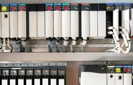
When a Schneider Electric TWDAVO2HT analog output module drives a variable frequency drive and suddenly overheats, maintenance teams face a complex industrial automation challenge. Engineers often suspect internal module failure immediately. However, field experience across control systems proves that wiring errors, voltage backfeed, and impedance mismatches cause these thermal overloads long before permanent hardware damage occurs.

Understanding Voltage Signal Constraints and Backfeed Risks
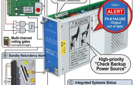
The 0-10V analog output generates precise control signals without providing external power to field devices. Accidentally wiring the PLC output to a VFD reference power terminal forces external voltage backward into the module. According to industrial maintenance reports, wiring cross-connections account for most analog channel burnouts.
Mitigating Electromagnetic Interference in Heavy Industrial Plants
Variable frequency drives generate severe electromagnetic interference that easily corrupts fragile voltage signals over long cable runs. Utilizing shielded twisted-pair cables and proper single-point grounding protects your PLC signals from stray ground loops. Furthermore, adding signal isolators in high-noise environments prevents erratic motor speeds and protects your valuable DCS equipment.
Step-by-Step Diagnostic Checklist
- ✅ Disconnect the VFD analog input wire and verify if the PLC module temperature returns to normal.
- ⚙️ Measure static voltages across the output terminals to detect unauthorized external power backfeed.
- 🔧 Confirm that the VFD analog input parameter matches the 0-10V voltage configuration.
- ✅ Inspect signal cable shielding and ensure proper single-point grounding at the control cabinet.
- ⚙️ Install a signal isolator if long cable runs suffer from high motor noise interference.
Application Scenarios: Root Cause Analysis
Scenario A: Accidental Power Backfeed
If an engineer wires the PLC output directly to a VFD +10V reference terminal, the resulting voltage backfeed overheats the output driver chip instantly.
Scenario B: Parameter Mismatch Failures
If the PLC outputs a 0-10V voltage signal while the VFD expects a 4-20mA current signal, the drive reports an input fault and the motor fails to track speed.
Frequently Asked Questions
Q1: Does an overheating TWDAVO2HT module always indicate internal hardware failure?
No. Overheating typically stems from external voltage backfeed, wiring cross-connections, or mismatched load impedances rather than inherent manufacturing defects.
Q2: What should I check first when my VFD fails to respond to 0-10V signals?
Always measure the voltage output directly at the PLC terminals and verify that your VFD analog input parameter matches the voltage control mode.
Q3: How do I ensure full compatibility when sourcing a replacement analog module?
Match your exact part numbers, output signal types, and system software configurations.