Understanding the IS210AEAAH1BHB Analog Auxiliary Board in GE EX2100 Excitation Systems
The Core Application Value in Power Generation Control Systems
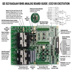
The GE IS210AEAAH1BHB functions as a vital analog signal conditioning interface within the EX2100 Excitation System. This board directly supports the excitation regulator during closed-loop control operations. In standard turbine-generator setups, it manages the automatic voltage regulation loop and field current feedback loop. Consequently, it stabilizes generator terminal voltage and control outputs during unpredictable grid fluctuations. This reliable operation prevents sudden system trips across complex petrochemical plants and heavy-duty industrial automation facilities.
Maximizing Analog Conditioning Accuracy for Voltage Loop Stability
The IS210AEAAH1BHB board processes critical analog feedback data including terminal voltage and exciter field current. It safely forwards these conditioned signals to the regulator section of the Mark VI or Mark VIe DCS controller. Signal drift or analog noise can compromise the automatic voltage regulator response. As a result, plants may experience voltage overshoots during sudden load rejections. Maintaining accurate analog scaling remains critical to ensure proper power factor control and smooth transient recovery.
Optimizing Response Dynamics in Field Current Regulation Loops
Beyond voltage regulation, this auxiliary board manages the field current loop by transmitting analog feedback from shunt measurement circuits. The performance of this analog path influences exciter forcing response and rotor thermal protection coordination. During rapid turbine startup sequences, field current demands can shift dramatically. If signal filtering becomes unstable, operators face field build-up delays or false limiter interventions. Therefore, this component acts as a high-precision bridge between the power section and digital control algorithms.
Overcoming Noise Obstacles and Ensuring Long-Term Reliability
Gas turbine excitation cabinets present harsh electrical environments filled with high-current DC fields and switching noise. The IS210AEAAH1BHB incorporates advanced isolation and filtering components to mitigate common-mode interference. This specialized design proves essential for offshore platforms and coastal factory automation facilities exposed to high humidity. Many mysterious voltage instability cases stem from degraded analog grounding paths rather than actual controller CPU faults. Therefore, clean signal pathways remain paramount for continuous plant operation.
Essential Field Installation and Maintenance Procedures
Successful commissioning requires verifying all grounding references before energizing the excitation panel. Floating analog grounds can skew voltage feedback scaling, which mimics severe control loop instability. In high-vibration turbine environments, mechanical stress frequently loosens terminal connections. Technicians should utilize ferruled conductors and apply specific torque ratings to prevent signal interruption. Moreover, routine outage inspections must include checking older electrolytic capacitors for thermal discoloration or physical swelling.
Strategic Procurement Insights from Oiltech Controls Limited
At Oiltech Controls Limited, we emphasize that treating this board as a precision control interface minimizes long-term operational risks. While many industrial automation components appear physically identical, firmware revisions dictate true backward compatibility. Mixing incompatible board suffixes can cause scaling mismatches or initialization faults during system boot. Therefore, we highly recommend auditing your application configuration files before sourcing replacement hardware.
For certified GE components and expert engineering support, visit Oiltech Controls Limited to keep your turbine control systems operating at peak efficiency.
Technical Field Checklist
- ✓ Grounding Audit: Confirm analog common grounding continuity before panel power-up.
- ✓ Vibration Defense: Deploy ferruled conductors and separate low-voltage analog lines from SCR firing cables.
- ✓ Lifecycle Inspection: Evaluate electrolytic capacitors for heat degradation during scheduled outages.
- ✓ Compatibility Check: Verify functional revision suffixes against Mark VIe software baselines before installation.
Frequently Asked Questions
Q1: Why is my excitation system experiencing voltage drift despite having a stable controller CPU?
Voltage drift often points to thermal aging of the analog interface components rather than a CPU defect. Over eight to ten years of continuous operation in warm cabinets, auxiliary board components can exhibit analog offset errors that skew the feedback loop.
Q2: How can I distinguish between a true field instrument fault and an auxiliary board issue?
Review the trending data in your toolbox software. If the analog signal shows sudden spikes only during load changes or SCR firing transitions, the issue usually involves failing isolation components or poor shield termination on the interface board.
Q3: Can I install a newer revision of this board into an older excitation cabinet configuration?
Hardware backward compatibility depends heavily on your specific firmware revision and system I/O mapping. You must cross-reference the board suffix with your configuration files to prevent system initialization errors upon startup.
Industrial Solution Scenario: Eliminating Commutation Noise
A petrochemical processing facility experienced intermittent reactive power hunting on a gas turbine generator during peak load shifts. Field technicians suspected a tuning issue within the core PLC control logic. However, an isolation audit revealed that commutation noise from the SCR bridge was bleeding into the voltage feedback loop. By replacing the degraded auxiliary interface board and correcting the single-point shield grounding at the cabinet side, the plant successfully restored voltage loop stability and eliminated the nuisance alarms.