Troubleshooting GE EX2100 IS210AEAAH1BJE Board Failures and Voltage Feedback Loss
Understanding the Impact of Excitation Board Faults
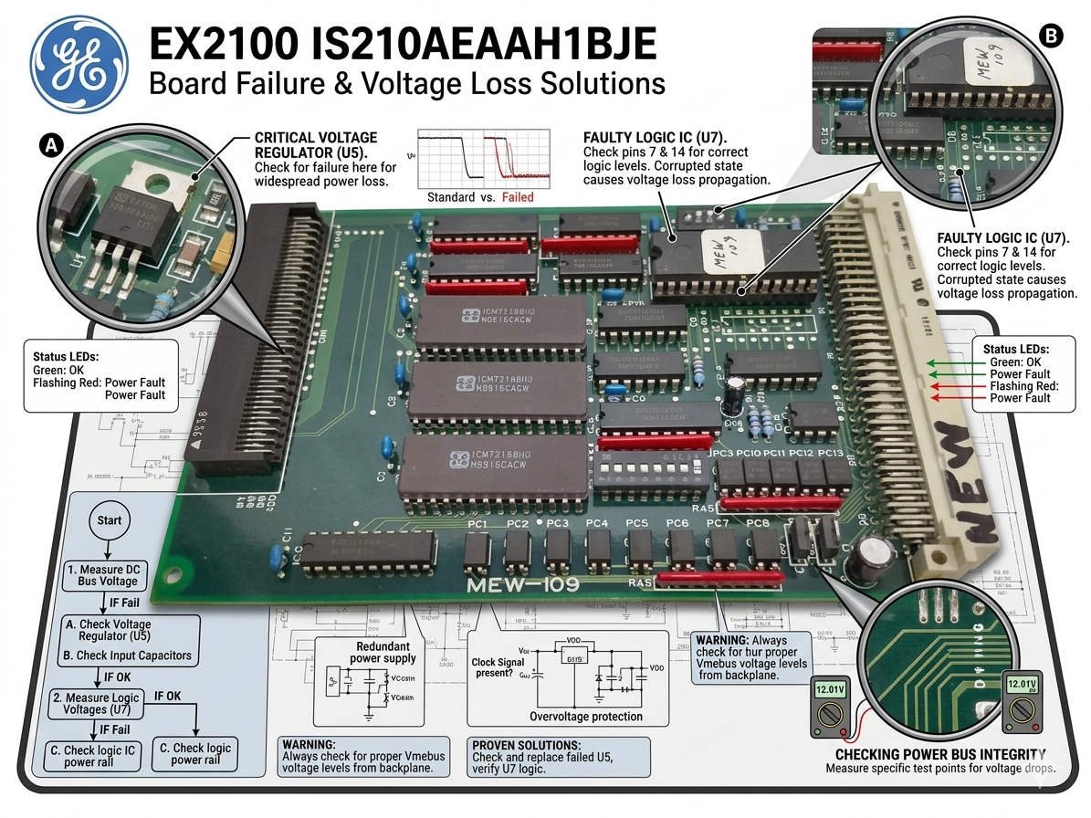
When the IS210AEAAH1BJE analog acquisition board fails inside a GE EX2100 excitation system, consequences materialize immediately. The Mark VI or Mark VIe controller typically triggers a severe “Generator Voltage Feedback Lost” alarm. Consequently, the system initiates a forced de-excitation sequence, tripping the field breaker or activating the crowbar circuit. In power generation and industrial automation setups, this fault often causes sudden generator load rejection and catastrophic turbine shutdowns.
The Core Strategy of Emergency Excitation Management
Managing an emergency goes beyond merely keeping a generator online. The primary objective centers on maintaining Automatic Voltage Regulator (AVR) reference integrity to execute a controlled shutdown. Uncontrolled reactive power oscillations can destabilize local power networks, particularly in petrochemical and captive generation plants. Therefore, stabilizing the voltage loop takes priority over short-term production continuity during a critical feedback failure.
Analyzing Generator Voltage Feedback Disruption
The IS210AEAAH1BJE card converts analog terminal voltage measurements for the primary control loops. If this feedback signal drops out, the AVR perceives a zero-voltage condition on the stator. As a result, the excitation system increases the rotor current aggressively, risking rapid over-excitation. Field operators frequently report that the AVR display drops to zero even when physical PT secondary voltages remain completely normal.
Pinpointing the Root Causes of Analog Drift
Intermittent alarms usually precede total hardware failure in the field. These early warnings point to analog-to-digital (A/D) conversion instabilities or power supply ripple. Furthermore, oxide layer accumulation on the backplane connectors can corrupt low-voltage analog signals. Our engineering team at Oiltech Controls Limited recommends inspecting these interfaces before ordering replacement circuit boards.
Evaluating Protection Coordination and Response Time
The EX2100 digital protection logic responds within milliseconds to protect the generator rotor insulation. However, overly aggressive trip settings can cause massive voltage dips across an entire industrial automation facility. Experienced technicians always evaluate potential loose connections at the TBQB or TBQC terminal blocks. This verification prevents engineers from replacing expensive hardware when simple wiring faults are to blame.
Environmental Threats to Cabinet Electronics
Corrosive atmospheres in chemical facilities and high humidity in coastal plants accelerate component degradation. Specifically, sulfur accumulation attacks Euro-style pin connectors, causing subtle signal drift. To mitigate these risks, operators must maintain cabinet temperatures below 35°C and relative humidity below 60%. Moreover, isolating the excitation system analog ground from heavy variable frequency drive (VFD) cabling minimizes high-frequency noise injection.
Emergency Handling Procedures for Plant Operators
If the generator trips due to a feedback fault, technicians must verify the physical PT circuit immediately. In redundant EX2100 configurations, compare the real-time values across the R, S, and T controller channels. If only a single channel shows deviation, isolate that specific path to allow temporary, controlled recovery. Never force manual AVR control blindly, because doing so dramatically increases the risk of catastrophic rotor over-fluxing.
Hardware Inspection and Mechanical Stability Guidelines
During scheduled plant maintenance, extract the module to check for thermal discoloration on the backplane pins. High-vibration environments near steam or gas turbines require additional mechanical counter-measures. Consequently, engineers should install secondary cable restraints and anti-vibration locking clips. These small adjustments effectively eliminate intermittent signal dropouts caused by structural resonance.
Procurement Strategies and Revision Compatibility
Before purchasing a replacement card, confirm your specific system architecture and firmware revision level. The IS210AEAAH1BJE board is not universally backward compatible across all legacy EX2100 setups. Mismatched EEPROM configurations or I/O pack mapping can cause immediate startup initialization failures. Therefore, you must verify the bill of materials (BOM) history rather than relying solely on visual hardware similarities.
Expert Recommendations from Oiltech Controls Limited
At Oiltech Controls Limited, we consider the EX2100 excitation system a highly reliable asset when maintained correctly. Our field data indicates that over 40% of voltage feedback errors originate from poor shielding and terminal corrosion rather than board failures. We highly recommend performing an offline loop simulation after any card replacement to guarantee correct scaling and controller channel voting.
For certified GE components, professional system diagnostics, and tailored control system upgrades, please visit Oiltech Controls Limited to consult with our engineering specialists.
Technical Essentials for Maintenance Teams
- ✓ Isolate Grounds: Keep excitation analog common independent from high-current inverter grounds.
- ✓ Monitor Environment: Ensure control cabinets operate under 35°C to prevent analog component drift.
- ✓ Verify Scaling: Confirm firmware and EEPROM parameters match exactly during card replacement.
- ✓ Secure Connectors: Use anti-vibration clips on JX1 and JX2 plugs to counter turbine deck resonance.
Frequently Asked Questions
Q1: Why does the voltage feedback alarm clear itself intermittently?
This behavior usually points to thermal cycling or oxidation on the backplane connector pins. As cabinet temperatures fluctuate, microscopic expansion changes the contact resistance, resulting in transient signal loss that triggers the Mark VIe diagnostic alarm.
Q2: Can we modify the controller voting logic to ignore a single channel failure?
Yes, in TMR (Triple Modular Redundant) architectures, the system can vote out a single faulty channel. However, you should only perform this isolation temporarily while preparing for a card replacement, ensuring the remaining two channels are perfectly healthy.
Q3: How do we differentiate between a physical PT failure and a board acquisition fault?
Measure the AC voltage directly at the cabinet incoming terminal block with a calibrated multimeter. If the physical voltage is balanced and correct, but the toolbox software displays zero or fluctuating values, the issue lies within the analog board conversion circuit.
Industrial Solution Scenario: Petrochemical Cogeneration
During a routine production cycle at a major refinery, a captive generator experienced sporadic voltage feedback alerts. The onsite maintenance team, following protocols established by industry standards, utilized a spare channel tracking configuration to verify signal health. They discovered severe sulfur corrosion on the backplane interface of the active analog board. By implementing a managed channel transfer, they safely avoided an un-programmed plant shutdown, saving the facility significant operational expenses.