Troubleshooting ABB UFC719AE01 Flashing Red STATUS Light: Expert Solutions
Understanding the Critical Diagnostic Alarm on ABB Control Systems
The ABB UFC719AE01 serves as a vital gate control interface board within high-power excitation and drive systems. When the STATUS indicator flashes red, it signifies a specific operational error. Field experience confirms that this flashing alert points directly to an inverter bridge failure. However, technicians often make the mistake of inspecting the rectifier bridge first. Consequently, misdiagnosing the primary source of the fault significantly increases unnecessary equipment downtime.
Strategic Operational Value of the UFC719AE01 Gate Control Board
In continuous process industries like metallurgy, power generation, and chemical processing, system stability is critical. The UFC719AE01 board orchestrates thyristor bridge firing logic and monitors real-time operation. Therefore, any fault in the bridge arm increases the risk of commutation failure or phase loss. The flashing red STATUS indicator acts as an essential diagnostic tool. It allows maintenance teams to bypass the rectifier circuit and isolate the problem immediately.
Dual Bridge Synchronization and Control System Logic
Large DC drives and excitation systems rely on precise coordination between the rectifier and inverter stages. While the rectifier establishes the DC bus energy, the inverter manages commutation and power regeneration. A flashing red indicator typically means the system has detected a non-conducting thyristor or a synchronization failure. As a result, the control loop may experience torque fluctuations, triggering an automatic safety interlock trip.
Fiber Optic Communication and Precision Signal Integrity
High-power ABB control systems require high-speed synchronous firing pulses delivered over fiber optic cables. If fiber attenuation, oxidized connectors, or ground noise disrupts this path, synchronization fails. In modern industrial automation architectures, a solid red light indicates permanent hardware failure. Conversely, a flashing red light indicates a logical synchronization issue. Consequently, technicians should verify the communication links before replacing expensive power components.
Mitigating Electromagnetic Interference in Harsh Factory Automation Environments
Industrial environments expose control electronics to severe electrical stress, high dv/dt, and severe power ripples. Often, intermittent flashing indicators do not stem from a faulty circuit board. Instead, poor cabinet grounding, tight fiber bending radiuses, or excessive 24V power supply noise cause the failure. ABB designs its systems to stringent IEC 61326 EMC standards. Therefore, maintaining strict installation discipline ensures long-term operational reliability.
Field Installation and Systematic Maintenance Guide
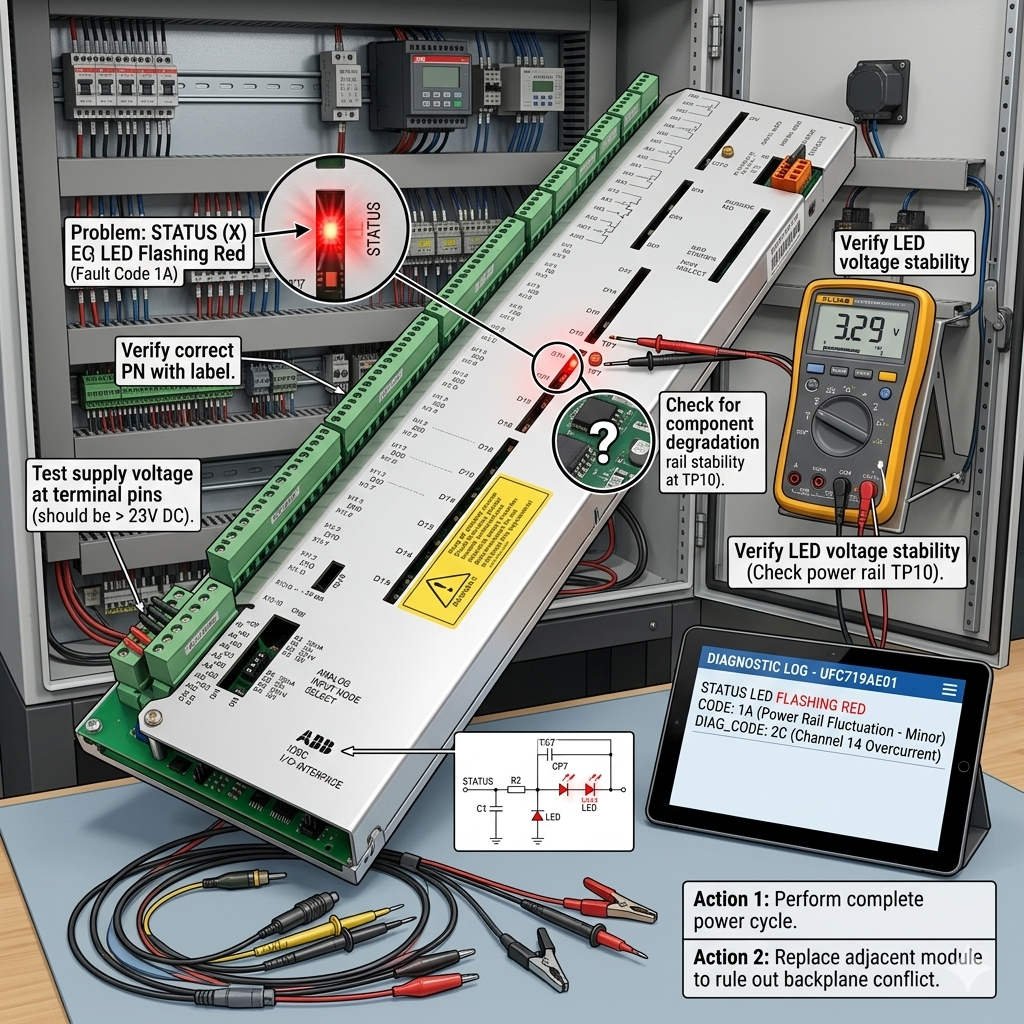
When the system triggers a flashing red alarm, follow a structured isolation sequence to resolve the issue quickly. First, verify the fiber optic connections on the inverter side. Next, measure the gate drive power supply voltage. Finally, check the synchronization pulse waveforms with an oscilloscope. Avoid removing power semiconductor modules before ruling out these fundamental control link issues.
Industrial Automation Insights from Oiltech Controls Limited
At Oiltech Controls Limited, we observe that nearly half of all drive system alarms originate from external connection issues rather than hardware failure. In high-vibration applications like cement mills or mining hoists, connectors frequently loosen over time. We recommend securing fiber cables with industrial-grade ties and conducting annual thermal imaging inspections. This proactive approach prevents unexpected trips and reduces overall maintenance overhead.
For certified replacement modules, expert system diagnostics, and tailored engineering support, visit our technical catalog at Oiltech Controls Limited to optimize your plant infrastructure.
Essential Field Diagnostic Checklist
- ✓ Isolate the Bridge: Focus diagnostic testing on the inverter bridge components.
- ✓ Inspect Fiber Optics: Check for physical damage, tight bends, or loose couplings.
- ✓ Measure Supply Quality: Verify that the 24V DC control power lacks excessive ripple voltage.
- ✓ Review Grounding: Ensure a single-point control ground to minimize high-frequency noise.
Frequently Asked Questions
Q1: Does a flashing red indicator mean the gate interface board is permanently broken?
No, a flashing light typically indicates a synchronization loss or a signaling anomaly rather than a catastrophic hardware breakdown. You should fully check the gate pulse cables, external power supplies, and thyristor continuity before replacing the board.
Q2: Why does this alarm occur intermittently after a heavy motor start?
Heavy loads often introduce electrical noise or momentary voltage sags into the control cabinet. If the signal lines lack adequate shielding, electromagnetic interference can corrupt the synchronization pulses, causing temporary alarms.
Q3: Can I swap this module between different generations of ABB excitation systems?
You must verify the embedded firmware version and backplane interface configurations first. Even if the physical dimensions match, incompatible software protocols or mismatched firing angle configurations can cause immediate commutation failures.
Application Scenario: Excitation Control in Power Generation
During a routine inspection at a hydro-power facility, a generator excitation system suffered from a sudden flashing red fault on the control board. The engineering team immediately suspected a damaged thyristor module. However, utilizing the systematic approach recommended by Oiltech Controls Limited, they checked the fiber optic links first. They discovered an over-bent fiber optic cable that attenuated the timing pulse, allowing them to restore full operation within minutes without replacing major components.