Troubleshooting AC 800PEC Trigger Pulse Enable Signals When ABB 3BHB003154R0101 Has No Output
The Vital Role of Firing Control in Generator Excitation Systems
In power generation and industrial automation, the ABB AC 800PEC controller acts as the brain for thyristor firing pulse delivery. It pairs directly with the ABB 3BHB003154R0101 trigger board to regulate field current in synchronous motors and generators. When this hardware setup fails to generate a pulse output, the entire excitation loop collapses, causing immediate automatic voltage regulator (AVR) lockouts. Consequently, understanding how to isolate the root cause prevents prolonged downtime in critical utility applications.

Decoding the Permissive Logic Chain Before Hardware Diagnostics
The ABB 3BHB003154R0101 board does not generate gate firing pulses independently. Instead, the AC 800PEC software architecture strictly governs its behavior via a complex permissive matrix. Key variables like converter readiness, field breaker status, and cooling system data must register as healthy. Therefore, if the software flag EnablePulse remains low, the control system intentionally suppresses output to safeguard the thyristor bridge from catastrophic short circuits.
Navigating the AC 800PEC Diagnostic Interface Safely
Field engineers must prioritize checking software parameters over physical board swapping during a fault event. You can access these vital statuses by opening the PEC Manager utility and navigating directly to Runtime Diagnostics. Within the Signal Viewer application, look for variables labeled PulseEnable, FiringEnable, or GateEnable. If the viewer displays a logical FALSE status for these tags, the control systems are actively blocking the hardware from triggering.
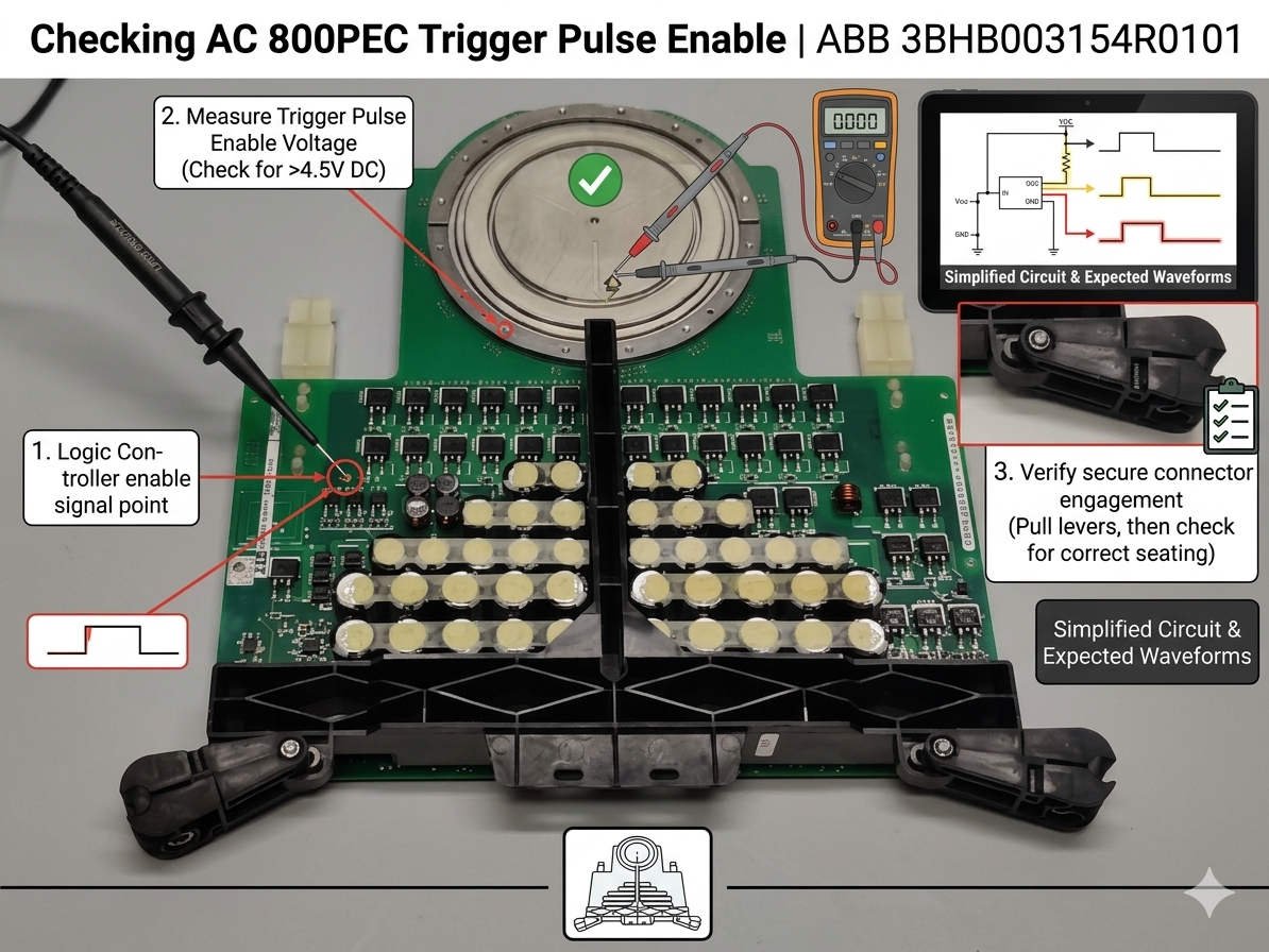
Implementing a Multi-Layered Signal Verification Strategy
Relying solely on software feedback can compromise safety in harsh, high-noise manufacturing facilities. Plant technicians should employ a rigorous three-tiered diagnostic process during excitation failures. First, verify the controller logic state inside the signal viewer. Second, track optical transmissions using a specialized fiber-optic pulse tester. Finally, evaluate the physical gate output wave using an isolated oscilloscope to ensure the hardware accurately executes software commands.
Installation Standards and Signal Protection Benchmarks
Physical circuit validation requires deep familiarity with industrial electromagnetic compatibility (EMC) guidelines like IEC 61326. Vibration-heavy environments near turbine decks can slowly unseat backplane connections or loosen fiber-optic terminations over time. When performing waveform analysis on the thyristor gate, technicians must utilize completely isolated voltage probes. This practice prevents stray grounding loops from destroying sensitive logic circuits on the controller rack.
Expert Automation Perspectives from Oiltech Controls Limited
At Oiltech Controls Limited, field statistics show that over 50% of missing trigger pulse incidents stem from external interlock issues rather than hardware failure. We frequently find broken dry contacts on field breakers or fouled fiber connections masquerading as dead circuit boards. Rushing to replace specialized components without a systematic logic trace inflates your spare inventory costs needlessly. We highly recommend mapping out all upstream protective interlocks before condemning an expensive component.
For certified replacement parts, detailed component documentation, and professional engineering support, explore our extensive inventory at Oiltech Controls Limited today.
Essential Field Verification Checklist
- ✓ Monitor Software Status: Verify that the
PulseEnablebinary tag equals TRUE within PEC Manager. - ✓ Inspect Optical Paths: Ensure fiber-optic cables are free of bends, dust contamination, or reversed TX/RX connections.
- ✓ Audit Loop Resistance: Check auxiliary relay contacts for high resistance that might block permissive signals.
- ✓ Check Seating Alignment: Confirm the module is firmly locked into the rack backplane to prevent intermittent bus faults.
Industrial Solution Scenario: Resolving Intermittent Excitation Lockouts
During a post-maintenance startup at a combined-cycle power plant, a synchronous generator experienced immediate excitation failure due to zero pulse output. The maintenance crew initially blamed a faulty 3BHB003154R0101 board. However, a rapid signal analysis via the PEC Manager revealed that the GateEnable bit stayed at zero. Technicians eventually traced the cause to a misaligned auxiliary contact on the main field circuit breaker, successfully restoring operations without deploying a single spare part.
Frequently Asked Questions
Q1: Why does the AC 800PEC software show a true enable signal while the fiber port remains dark?
This mismatch typically indicates a component-level hardware issue within the optical transmitter circuit of the board. If the backplane voltages test fine and the slot is securely seated, the internal gate driver IC may have failed, requiring a module replacement.
Q2: Can I substitute different revisions of the 3BHB003154R0101 board during an emergency?
We strongly advise against blind substitution. Different engineering suffix codes often denote changes in optical frequency, timing characteristics, or thyristor compatibility. Always verify your specific application firmware package version against the manufacturer reference manual before swapping components.
Q3: What causes an active overvoltage trip to lock out the firing pulse completely?
The crowbar protection circuit forces a firing lockout to shield the main bridge from excessive back-EMF or lightning surges. The system routes this high-priority safety interlock through hardware lines to bypass standard software routines, ensuring near-instantaneous component protection.


