Troubleshooting ABB UNS4684A HIEE305114R0001: How to Diagnose Missing Firing Pulses
The Role of Pulse Amplifiers in Generator Excitation Failure
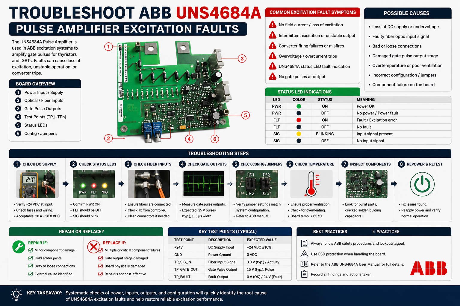
Excitation failure frequently stems from issues within the gate driver circuitry rather than the main controller. The ABB UNS4684A HIEE305114R0001 pulse amplifier board drives the Silicon Controlled Rectifier (SCR) rectifiers. This component amplifies low-level control pulses into high-energy signals required for thyristor conduction. Consequently, a missing or degraded pulse prevents the excitation voltage from building up during startup sequence phases.

Why Signal Isolation Matters for Thyristor Gate Drive Stability
The ABB UNS4684A relies on robust pulse transformers instead of standard optical couplers to ensure reliable signal isolation. This design choice provides high common-mode noise rejection in harsh factory automation environments. Therefore, the board shields delicate control loops from high dv/dt transients generated during thyristor commutation. Without this electrical isolation, electromagnetic interference can degrade the firing command, causing intermittent startup failures.
Analyzing Pulse Width and Amplitude During Startup Sequences
A stable analog voltage reading on a standard multimeter does not guarantee a proper SCR gate trigger. SCR gates demand a specific current amplitude and pulse width to achieve full silicon latching. If the pulse width collapses during the field flashing phase, the thyristor will remain non-conductive. As a result, engineers must evaluate the pulse train dynamically under actual load conditions rather than relying on static tests.
The Critical Impact of Synchronization Signal Disruption
An excitation system can generate firing pulses but still fail to build voltage if phase synchronization is lost. The Automatic Voltage Regulator (AVR) coordinates firing angles relative to the main generator voltage phase. However, wrong phase sequences or faulty potential transformer inputs lead to incorrect firing angles. This misalignment causes a net zero output from the bridge, leaving the generator completely unexcited.
Step-by-Step Field Diagnostic Procedures for Maintenance Teams
Field technicians can quickly isolate a pulse amplifier malfunction using specific diagnostic steps. First, measure the gate-to-cathode voltage dynamically using an isolated channel oscilloscope. Second, inspect the pulse transformer secondary windings for open-circuit faults or driver transistor failures. Finally, monitor the anode-to-cathode voltage drop across the thyristors to verify whether the semiconductor layer actually achieves full conduction.
Mechanical Stability and Electrical Shielding Practices
High-vibration plant areas often accelerate mechanical wear on gate driver card edge connectors and wiring terminals. Over time, terminal oxidation and loose terminal screws mimic complete component failure by causing intermittent signal dropouts. Furthermore, engineers must separate gate drive cabling from high-voltage motor lines. Implementing single-point grounding according to IEC 61326 standards effectively preserves signal integrity in noisy compressor rooms.
Strategic Procurement Insights from Oiltech Controls Limited
At Oiltech Controls Limited, we observe that many gate driver issues track back to component aging. Electrolytic capacitor degradation and micro-cracks in solder joints often cause temperature-dependent excitation trips. If your system exhibits erratic behavior when warm, consider proactive replacement of the board. Moreover, always cross-reference part numbers and firmware revisions before installing a replacement to avoid destructive misfires.
For certified replacement parts and specialized control systems expertise, explore the component inventory at Oiltech Controls Limited to protect your generation assets.
Technical Troubleshooting Checklist
- ✓ Verify Phase Sync: Inspect potential transformer connections to ensure accurate phase sequencing.
- ✓ Measure Gate Waveforms: Capture firing pulse profiles using high-bandwidth isolated oscilloscope probes.
- ✓ Audit Loop Tightness: Torque all gate-cathode connection screws to prevent vibration-induced dropouts.
- ✓ Isolate Cabling: Route all pulse command lines away from high-current power cables.
Frequently Asked Questions
Q1: Why does the pulse amplifier show normal inputs but fail to output gate currents?
This condition usually points to an onboard power supply rail failure or a blown driver transistor. The logic circuit may function correctly, but the output stage lacks the energy to drive the pulse transformer primary winding.
Q2: Can a faulty thyristor trick me into thinking the ABB board is dead?
Yes, an internal gate-to-cathode short circuit within the thyristor will clamp the pulse amplifier output voltage near zero. Disconnect the gate lead and re-test the board output to determine if the fault lies in the electronics or the power semiconductor.
Q3: How do I know if the replacement board is fully compatible with older UNITROL systems?
You must verify the exact hardware revision suffix alongside the main HIEE part number. Some legacy systems utilize different pulse polarities or distinct pin assignments, making visual matches unreliable for system protection.
Industrial Solution Scenario: Black Start Optimization
During a critical black start compliance test at a major thermal power facility, the turbine excitation system failed to build voltage. Initial assessments suspected the main controller logic. However, field technicians verified that the pulse widths from the UNS4684A collapsed due to excessive noise on unshielded lines. Replacing the lines with shielded twisted pairs restored stable firing pulses and allowed successful voltage buildup on the next attempt.


%20rectifiers.%20This%20component%20amplifies%20low-level%20control%20pulses%20%5B…%5D&media=https://www.oiltechcontrols.com/wp-content/uploads/2026/05/Troubleshoot-ABB-UNS4684A-Pulse-Amplifier-Excitation-Faults.jpg)