Optimizing Control Stability: The Strategic Value of Feedforward Control in PLC Systems
Enhancing Process Reliability Beyond Standard PID Control
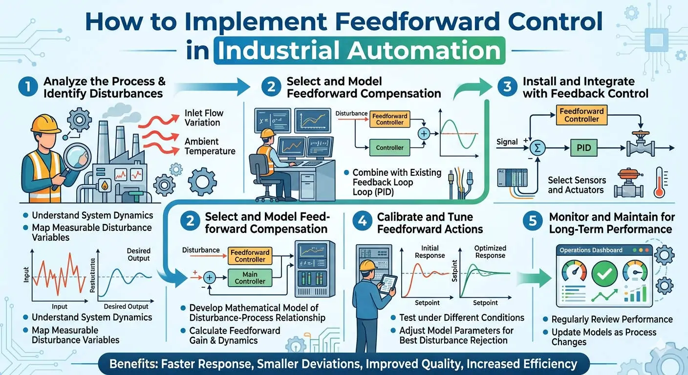
Standard PID control often struggles with large, predictable disturbances in complex industrial environments. These disturbances include sudden load changes or upstream process variations. Feedforward control addresses this gap by compensating for errors before they impact the process variable. Consequently, this proactive approach significantly improves system stability and response time. In high-stakes sectors like oil, gas, and chemical processing, combining PID with feedforward logic maintains tighter quality tolerances and reduces energy waste.
Ensuring Disturbance Measurement Accuracy for Reliable Logic
Feedforward success depends entirely on the accuracy of measurable disturbances, such as flow rate or temperature. Therefore, the signal quality and update rate directly determine how effectively the system compensates. Poor signal quality often leads to incorrect adjustments, which causes unwanted oscillations. Engineers should utilize transmitters that comply with IEC 60770 standards. In addition, implementing first-order low-pass filters within the PLC logic ensures the system processes clean, actionable data.
The Importance of Scan Cycle and Algorithm Execution Speed
In a PLC-based implementation, the system must calculate feedforward actions within a strict control cycle. If the PLC scan time is too slow, the feedforward action loses its predictive advantage. As a result, it begins to behave like a delayed feedback loop. For fast processes like flow or pressure control, we recommend maintaining control task cycles below 20 ms. Using high-priority cyclic interrupts ensures the algorithm executes without interference from standard program scans.
Dynamic Model Matching and Feedforward Gain Alignment
Feedforward control requires a process model to function effectively. The gain and dynamic matching between the disturbance and the control output are critical factors. Incorrect gain settings often lead to under-compensation or over-compensation. This increases the overall workload on the PID controller. Therefore, experts at Oiltech Controls Limited suggest starting with a steady-state gain. You can then add lead/lag compensation blocks to align the logic with the specific dynamics of the process.
Critical Installation and Maintenance Standards for Signal Sync
Signal synchronization is an aspect of control systems that engineers often overlook. In multi-variable systems, disturbance signals may arrive at the controller at different times than the actual process impact. For instance, in steam temperature loops, flow measurements often lead temperature changes by several seconds. To solve this, you should incorporate configurable delay blocks in the PLC logic. This alignment ensures the feedforward action coincides perfectly with the physical process response.
Expert Commentary from Oiltech Controls Limited
At Oiltech Controls Limited, we observe that many facilities underutilize feedforward capabilities because they fear complexity. However, moving from reactive to predictive control is essential for modern high-efficiency industrial automation. We recommend a “crawl-walk-run” approach when retrofitting. First, ensure your PID loop is stable independently. Then, introduce feedforward with a low gain of roughly 20%. This gradual integration prevents system destabilization while allowing for fine-tuning based on real-time field data.
For more insights on advanced control strategies and high-performance hardware, visit Oiltech Controls Limited to explore our technical resources and solutions.
Technical Implementation Checklist
- ✓ Signal Integrity: Verify that all disturbance transmitters are calibrated to IEC standards.
- ✓ Sync Logic: Add delay or lead/lag blocks to match the physical transport delays of the plant.
- ✓ Filter Settings: Apply digital filtering to prevent valve hunting caused by signal noise.
- ✓ CPU Load: Ensure the PLC processor load remains below 70% to maintain fast scan cycles.
Frequently Asked Questions (FAQ)
Q1: How do I determine if my loop requires feedforward or just better PID tuning?
If your process displays consistent, measurable disturbances that always cause a predictable deviation, feedforward is the right choice. However, if the fluctuations are random or the source cannot be measured accurately, you will achieve better results by optimizing your PID parameters or using adaptive control logic.
Q2: Can I implement feedforward on an older PLC system?
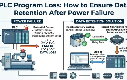
It depends on the processing speed. Older hardware may lack the memory or scan frequency to handle advanced dynamic compensation. Before upgrading, check if your PLC supports Structured Text (ST) or high-priority interrupts. If the CPU load is already high, a hardware migration or a dedicated DCS module might be necessary to avoid control lag.
Q3: Why does my feedforward action cause the control valve to vibrate?
This “valve hunting” is usually caused by noise amplification. Because feedforward paths lack the natural damping of a PID integral term, they are highly sensitive to raw signal jitter. To fix this, increase the digital filtering on the disturbance input and ensure your signal cables use proper shielding and grounding per IEC 61158 standards.
Typical Solutions Scenario: Steam Boiler Control
In steam boiler drum level control, a “three-element” strategy is often used. The system measures steam flow as a disturbance variable. When steam demand increases, the feedforward logic immediately increases feedwater flow. This happens before the drum level actually drops. Consequently, the system maintains a stable level despite rapid load changes, preventing low-water trips and improving boiler efficiency.


